Vacuum conveying is simple in principle: material is sucked through a conveying tube by vacuum pumps located upstream of the delivery point. It can provide either steady or batched delivery of materials between production stages and flexible routing through industrial plants, protecting the material en route.
The advantage of vacuum driven systems is that the pressure prevents leakage, maintaining a safe environment and minimising wastage. Although vacuum conveying tends to restrict your choice of delivery points (it must be near the compressor), it can readily pick up from a variety of different locations, such as a succession of delivery vehicles or hoppers dispensing different ingredients. A simple animation of a vacuum conveyor can be watched here: https://www.youtube.com/watch?v=xZBC6viI-Fw.
Vacuum conveyors readily handle granules from ½ micron in size up to 50 mm, moving as much as 10 tons per hour. Runs of 150m or more are possible but tend to become prohibitively expensive compared to positive pressure conveying.
Dilute or Dense Conveying
Vacuum conveyors can be operated with either a “dilute” or “dense” proportion of air to transported material. Dilute phase conveyors use a relatively high amount of air to transport the material, so keeping it almost perpetually airborne, whereas a dense phase system tumbles it through more gently. The latter are more restricted in scale but required by some materials.
Design of vacuum conveyors requires a specialist company such as http://www.aptech.uk.com/pneumatic-conveying/vacuum-conveying/. The required rates and pressures for the given material must be calculated carefully and components matched to maintain steady uninterrupted flow through the system.
Components in a Vacuum Conveyor
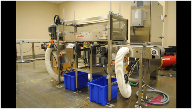
A vacuum pump is located near the delivery point, so a certain amount of headroom is required to accommodate it (although work-arounds are often possible).
Airlocks need to be located at the discharge of a vacuum system. This is usually a rotary valve, but butterfly valves, flapper valves, slide gates, knife gates and other devices are also common.
The material-to-air ratio must be metered and regulated. Devices used for this can be as simple as a material feeder like a rotary valve or screw, but in some cases complex air inlet management systems are installed.
The material and air must be separated again, so devices used to do this include things like cyclones or pulse-jet fabric bag houses of felt or spun bound polyester.